Quick answer: Valve actuator integration means fitting a valve, gearbox, and actuator together so they work as one unit. To do it right, confirm the valve torque and top flange, decide if the actuator needs a gearbox, design the mounting kit, add limit switches and feedback, decide on manual override, then assemble and test the full unit before it leaves the factory.
Most automation problems on site are not actuator problems. They are fitting problems. The bracket is a few millimetres off, the coupling slips, or the limit switch shows “open” when the valve is half closed.
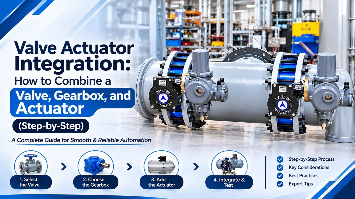
At Relekon Automation, we build complete valve automation solutions for OEMs and EPC contractors. These are the six steps we follow on every package:
- Confirm the valve torque and top flange
- Decide: direct actuator or actuator + gearbox
- Design the mounting kit (bracket + coupling)
- Add limit switches and position feedback
- Decide on manual override
- Assemble, set the stroke, and test
What each part does in an automated valve
An automated valve is five parts working together. If one part is wrong, the whole unit fails.
| Part | What it does | What to check |
|---|---|---|
| Valve | Opens and closes the flow | Maximum torque, top flange, stem size |
| Gearbox | Multiplies the actuator’s torque | Rated torque, gear ratio, turns to close |
| Actuator | Turns the valve or gearbox using power (electric or air) | Output torque, speed, input flange |
| Mounting kit | Bracket and coupling that join the parts | Alignment, drive size, strength |
| Accessories | Limit switch box, position indicator, manual override | Signal type, mounting pad, site needs |
For small valves, the actuator can turn the valve directly. For larger valves, an actuator operated gearbox sits between the actuator and the valve. Step 2 explains when you need one.
Step 1: Confirm the valve torque and top flange
Everything starts with the valve. You need three things from the valve maker’s datasheet or drawing:
- Maximum torque (Nm): the breakaway torque at full pressure. This is the highest torque the valve needs.
- Top flange: the ISO 5211 flange size on top of the valve, for example F10, F12, or F14.
- Stem details: drive type (square, keyway, or double D), size, and height.
Then add a safety margin. We usually start with 25-30% for clean service, and more for slurry, low temperature, or valves that sit unused for a long time.
Example: valve maximum torque = 1,200 Nm. With a 1.3 safety factor:
1,200 × 1.3 = 1,560 Nm required
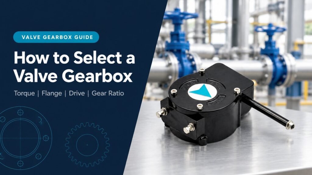
We’ll use this example in the next steps. For a full guide on torque and flanges, read how to select a valve gearbox.
Step 2: Direct actuator or actuator + gearbox?
You have two options:
- Direct mount: the actuator turns the valve by itself. Simple, fast, fewer parts. Good for small and medium valves.
- Actuator + gearbox: a smaller actuator drives a gearbox, and the gearbox turns the valve. Good for large valves and high torque.
Why add a gearbox? Cost and size. An actuator strong enough to turn a 1,560 Nm valve directly is large, heavy and expensive. A gearbox multiplies the actuator’s torque, so a much smaller actuator can do the same job.
Example with a gearbox: our RAE-W2200 actuator gearbox is rated 2,200 Nm with a mechanical advantage (MA) of 16.
Actuator torque needed = 1,560 ÷ 16 ≈ 98 Nm
So instead of a 1,560 Nm actuator, you need an actuator of about 100 Nm.
Relekon actuator-operated gearbox models (RAE series)
| Model | Torque (Nm) | MA (±10%) | Gear ratio | Turns to close | ISO 5211 valve side | ISO 5211 actuator side | Weight (kg) |
|---|---|---|---|---|---|---|---|
| RAE-W700 | 700 | 10 | 40:1 | 10 | F10, F12 | F10, F12 | 8.5 |
| RAE-W1000 | 1,000 | 12 | 44:1 | 12 | F12, F14 | F12, F14 | 12 |
| RAE-W1500 | 1,500 | 14 | 48:1 | 12 | F14 | F12, F14 | 14 |
| RAE-W2200 | 2,200 | 16 | 55:1 | 15 | F14, F16 | F14, F16 | 20 |
| RAE-W3500 | 3,500 | 20 | 73:1 | 20 | F16 | F14, F16 | 26 |
| RAE-W5000 | 5,000 | 50 | 90:1 | 66 | F16 | F16, F25 | 33 |
| RAE-W5500 | 5,500 | 65 | 90:1 | 66 | F16, F25 | F16, F25 | 45 |
| RAE-W7000 | 7,000 | 70 | 150:1 | 73 | F16, F25 | F16, F25 | 55 |
| RAE-W10000 | 10,000 | 75 | 300:1 | 80 | F25, F30 | F25, F30 | 80 |
Above 10,000 Nm, use a high torque actuator gearbox (worm + spur), available up to 100,000 Nm.
Two things people forget
1. The actuator must be able to turn many times: A quarter-turn worm gearbox needs several input turns for one 90° stroke. The RAE-W2200 needs 15 turns. A normal 90° actuator can’t do this, so you usually need a multi-turn electric actuator. If you plan to use a pneumatic actuator, tell us first, and we’ll suggest the right arrangement.
2. Check the stroke time: More turns mean a slower stroke.
Formula: Stroke time (seconds) = Turns to close × 60 ÷ Actuator speed (rpm)
For 15 turns and a 24 rpm actuator: 15 × 60 ÷ 24 = 37.5 seconds. If your process needs faster closing, choose a lower ratio or a faster actuator.
Step 3: Design the mounting kit (bracket + coupling)
The mounting kit is the small part that causes the biggest problems. It has two pieces:
- Bracket: holds the actuator or gearbox firmly on the valve.
- Coupling: connects the actuator shaft to the gearbox or valve stem, so the torque passes through.
What makes a good mounting kit:
- Correct alignment: The actuator shaft and valve stem must be in one straight line. Even a small offset wears the stem, bushes, and coupling quickly.
- Correct drive size: The coupling must match the stem exactly: square, keyway, or double D. A loose coupling creates play, and the valve does not fully close.
- Enough strength: The bracket and coupling must carry the full torque with margin, not just the running torque.
- ISO 5211 flanges on both sides: This makes the parts easy to fit and replace later.
Most actuator brands have their own flange and shaft details. Share the actuator make and model with us, and we will make the bracket and coupling to suit.
Step 4: Add limit switches and position feedback
An automated valve has to tell the control room what it’s doing. That’s the job of the feedback accessories.
| Accessory | What it does |
|---|---|
| Limit switch box | Sends “fully open” and “fully closed” signals to the PLC or control panel |
| Position indicator | Shows open or closed on the valve itself, so operators can see it from the ground |
| Torque limiter | Protects the valve and gearbox if the valve jams |
| Locking arrangement | Locks the valve in one position for safety or maintenance |
Plan this before the gearbox is made: A gearbox with limit switch provision has a ready mounting pad and shaft extension. Adding a switch box to a gearbox without this means drilling and adapters on site.
Set the switches correctly: The switch cams must be set to the real end positions of the valve, not the actuator’s limits. If they’re set wrong, the panel can show “closed” while the valve is still a few degrees open. We set them during assembly and test the signals before dispatch.
Step 5: Decide if you need a manual override
Ask one simple question: if the power goes off, does someone still need to open or close this valve?
If yes, add a manual override gearbox (MOR). It lets an operator turn the valve by hand wheel during a power cut, an emergency or actuator maintenance.
You usually need a manual override on:
- Fire water lines
- Water supply mains
- Emergency shutdown and isolation valves
- Valves at remote sites where power is not reliable
Relekon manual override (MOR) models
| Model | Torque (Nm) | Gear ratio | Turns to close | Hand wheel (mm) | Weight (kg) |
|---|---|---|---|---|---|
| RA-M125 | 125 | 40:1 | 10 | Ø150 | 3 |
| RA-M250 | 250 | 33:1 | 8 | Ø200 | 4.5 |
| RA-M500 | 500 | 40:1 | 10 | Ø250 | 6.5 |
| RA-M1000 | 1,000 | 44:1 | 12 | Ø350 | 13.5 |
| RA-M3500 | 3,500 | 73:1 | 20 | Ø500 | 30.5 |
For higher torque, MOR is available with worm + spur gearing up to 100,000 Nm.
Step 6: Assemble, set the stroke and test
A valve, gearbox and actuator that each pass their own test can still fail together. That’s why the full unit should be assembled and tested at the factory, not on site.
Our assembly and testing steps:
- Mount and align: fit the gearbox and actuator on the valve with the bracket and coupling, and check alignment.
- Set the end stops: adjust the gearbox stops so the valve opens and closes exactly 90°, with full seating at the closed position.
- Set the actuator limits: match the actuator’s open and close limits to the gearbox stops.
- Set the limit switches: set the switch cams to the real valve positions and check the signals.
- Cycle test: open and close the full assembly several times to check smooth operation, stroke time and signals.
- Pre-dispatch inspection: final check of fit, finish, coating and documents before packing.
The result is a ready-to-install unit. On site, your team bolts it onto the pipeline and connects power and signals. No fitting, no guesswork.
Common valve actuator integration mistakes
- Sizing the actuator by valve size, not torque: Two valves of the same size can need very different torque.
- Using a 90° actuator on a worm gearbox: The gearbox needs many input turns, so a 90° actuator can’t complete the stroke.
- Forgetting the stroke time: A high gear ratio with a slow actuator can make closing take minutes.
- Buying the valve, gearbox and actuator from three suppliers: Nobody owns the fit, and site teams end up modifying brackets.
- Setting limit switches to actuator limits, not valve positions: The panel shows “closed” when the valve is not fully closed.
- No manual override on critical valves: During a power cut, the valve can’t be operated.
Valve automation RFQ checklist
Send these details with your enquiry, and we can quote a complete package without back-and-forth.
| Item | Example |
|---|---|
| Valve type and size | Butterfly, DN 400 |
| Pressure class and media | PN 16, raw water |
| Valve maximum torque (Nm) | 1,200 |
| Top flange and stem drive | F14, square 36 mm |
| Actuator type | Electric multi-turn (make + model if fixed) |
| Power supply | 415 V, 3 phase, 50 Hz |
| Required stroke time | Under 60 seconds |
| Feedback needed | Limit switch box, position indicator |
| Manual override | Yes / No |
| Site conditions | Outdoor, coastal, 50°C ambient |
| Coating | Epoxy primer + epoxy finish |
| Quantity and delivery location | 12 nos, Dubai |
Get a complete valve automation package
Send us your valve details or the checklist above. Our engineers in Ahmedabad will size the gearbox and actuator, design the mounting kit, and supply the full unit assembled, set and tested, ready to install. We supply OEMs, EPC contractors and end users across India, the GCC and Europe, and we also take on customized valve gearbox projects for non-standard valves.
Get a free integration proposal
Call +91 97275 11990 or email relekonautomation@gmail.com.
Frequently asked questions
What is valve actuator integration?
Valve actuator integration is fitting a valve, gearbox (if needed), actuator, mounting kit and accessories together so they work as one automated unit. It covers torque sizing, mounting design, limit switch setting and testing of the full assembly.
How do I calculate the actuator torque needed with a gearbox?
Divide the required valve torque (with safety margin) by the gearbox’s mechanical advantage. For example, 1,560 Nm ÷ 16 = about 98 Nm, so an actuator of around 100 Nm can drive the valve through the gearbox.
Can I use a pneumatic actuator with a worm gearbox?
A standard pneumatic actuator turns only 90°, but a worm gearbox needs several input turns for one stroke. So worm gearboxes are usually paired with multi-turn electric actuators. Share your requirement and we will suggest the right arrangement for pneumatic service.
How do I calculate the stroke time of a gear-operated valve?
Multiply the gearbox’s turns to close by 60, then divide by the actuator speed in rpm. A gearbox with 15 turns and a 24 rpm actuator closes the valve in about 37.5 seconds.
Can an existing manual valve be converted to an automated valve?
In most cases, yes. We check the valve’s torque, top flange and stem, then design a mounting kit for the gearbox and actuator. Share the valve drawing or photos of the top works to start.
Should the valve, gearbox and actuator come from one supplier?
It is safer. When one supplier assembles and tests the full unit, one team is responsible for fit, settings and performance. With three suppliers, fitting problems usually show up on site.
What is the difference between a limit switch box and a position indicator?
A limit switch box sends open and closed signals to the control panel. A position indicator only shows the valve position visually on site. Most automated valves use both.